The Sturmey-Archer AW gearbox for Raleigh bicycles
In 1983 we visited the vast Raleigh bicycle factory in Nottingham. Raleigh was founded in 1885 and was one of the oldest and largest bicycle manufacturing companies in the world. It had been a very popular brand for many years and their three-speed hub gearbox was a major selling point. This ingenious hub had been designed by Henry Sturmey and James Archer and has remained essentially the same since the first model was produced in 1902.
The hub was completely enclosed (Image 1) thus reducing risks of material ingress into the gears and avoiding any chain problems when changing gear. This design increased reliability and simplicity to use, and well over 80 million were sold worldwide.
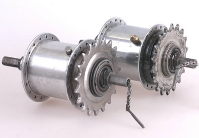
Image 1: Two rear-wheel hub gearboxes
Inside the hub things were more complex. The three gear ratios were achieved by means of a sun and planet system running inside an enclosing gear ring. A sliding clutch, moved by means of a small chain pulled by the rider, allowed selection of one of three different drive paths through the system. The total of distinct components numbers over 40 (Image 2) and all were made in the factory except for ball bearings and springs. The manufacturing process cover three stages: raw materials (40% of costs); component manufacture (30%); and assembly (30%). We were interested in assembly because automation in this area offers potential benefits of lower costs and improved reliability.
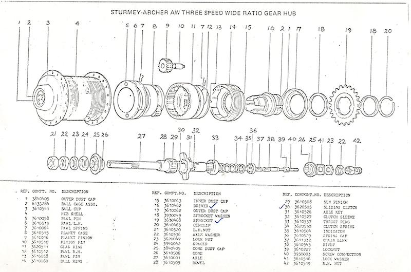
The component manufacturing processes involve forging, machining, punching, plating, and heat treatment. Components are then built into sub-assemblies at many manual workstations and assembled on a single line. There were nine subassembly tasks that were relatively simple, such as machine loading, and there were five different assembly operations on the main assembly line. We identified one of these as a candidate for experimentation: the assembly of the planet cage onto the axel. This was a bottleneck task – it was the slowest task, there were eight workstations dedicated to it, and it was critical to be error-free.
Image 3 shows a typical planet cage assembly workstation. The operator uses a jig which holds an axel vertically and then fits some components onto the axel: in this case, the planet cage and the planet gears and their holding pins. The operations were not difficult in themselves but required considerable dexterity and the operators were very skilled and very fast.
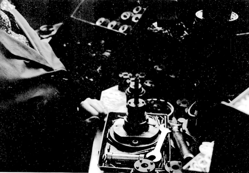
We decided to experiment with this assembly stage and (Image 4) shows the four component types we used. The planet cage A is to be inserted onto the axel D and then four planet wheels B are to be inserted into slots in the cage and each held in place with a pin C.

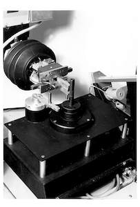
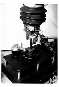
We built a number of jigs to hold parts and feeders to supply items to the robot. Image 5 shows the cages and axels being supplied to the robot on a rotary table, the assembly station (lower centre), a feeder for pins (to the right of the assembly station), an output table (further right), and a feeder for pinion wheels (above the output table). The robot hand (upper centre) has inbuilt force sensors and a precision two-finger gripper. The assembly station is shown in Image 6 where a pin is being inserted into a hole in the cage, this has to pass through the pinion gear to hold it in place. When all four gears have been pinned in the robot picks up the complete assembly and places it in a location in the output table (Image 7).
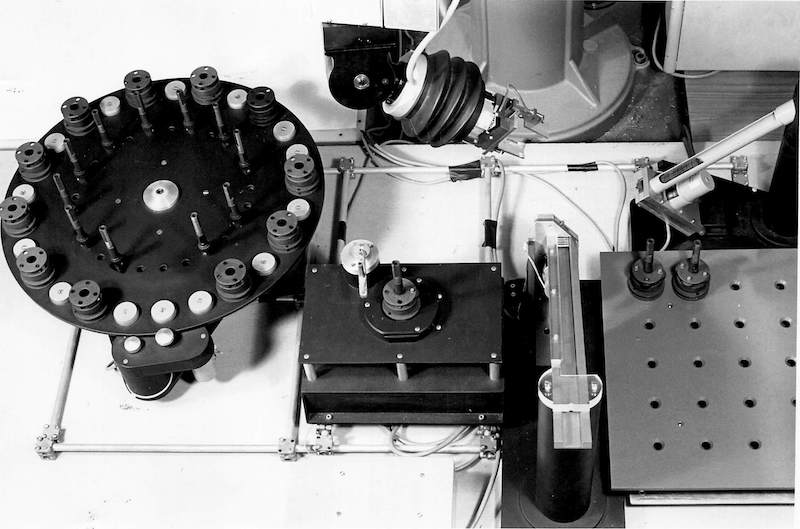
Our interest was in error detection and error recovery (at that time using rule-based and expert system ideas). The importance of reducing assembly errors is very clearly illustrated by this case study. The operators at Raleigh throw away any faulty parts they encounter and formal quality checks are included at over eight points in the assembly process but despite this faulty hubs are still found in the final test. The value added by combining all the parts is sufficient that Raleigh had a 'rectification' section that disassembled the reject hubs, corrected the problem, and reassembled for sale. Figures for error rates are difficult to obtain in most companies but looking at the stack of reject hubs one morning we estimated the error rate as being more than 7%.
Sadly the Raleigh empire fell apart in 2000. The factory was demolished in 2001 and Nottingham University bought the huge site and built another campus. Raleigh bicycles are now made by a Dutch company under licence, but there is a still an outlet in Nottingham: Raleigh UK Ltd. The Sturmey-Archer brand also still exists and they are now made by SunRace in Taiwan.
For further details see Robotics Research Report number 15/83.